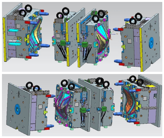
The design of injection molds for automotive headlights is a complex process due to the large scale and intricate parting surfaces. Many manufacturers utilize an integrated structure in their molds, where the fixed mold plate (A) forms the fixed part and the movable mold plate (B) forms the movable part. This structure offers several advantages, including compactness, good strength and rigidity, reduced mold volume, and streamlined processes.
1. Parting Surface Design
- Smooth Parting Surface: The parting surface should be smooth without sharp corners or thin areas. The YWX injection mold design employs methods like extension, sweeping, and mesh for splitting. The parting surface is shaped according to the plastic part, ensuring high conditions without wrinkles. CNC machining accuracy is maintained without EDM angle clearing, and high-speed machines with a spindle speed of at least 20,000 rpm are used.
2. Coordination Between Insert and Moving Die
- Process Inverted R Angle: An appropriate inverted R angle or clearance position is required at the seam root to simplify processing and improve efficiency.
3. R Angle Design
- Non-Forming Corners: R angles should be designed at all non-forming corners to prevent stress cracking, with a minimum of R5. Larger R angles are preferred to avoid accidents during operations.
4. Clearance of Parting Surface
- Width and Clearance: The parting surface width is 40mm, with a 1mm clearance between fixed and moving molds to reduce processing time. Venting holes are required to release compressed air during mold closing.
5. Parting Surface Construction
- Shape Optimization: The parting surface should be optimized based on the shape of the parts, with smooth production avoiding thin steel and sharp corners.
6. Smooth and Flat Parting Surface
- Avoid Small Broken Surfaces: Multiple small broken surfaces are not allowed; extended surfaces and grid surfaces are encouraged for construction.
7. S/O Angles
- Angle Design: All S/O angles on the parting surface should be higher than 7 degrees to extend the mold service life.
8. Assembly and Disassembly Method
- Insert Design: The insert design incorporates a 5-degree obliquity for easier assembly and disassembly.
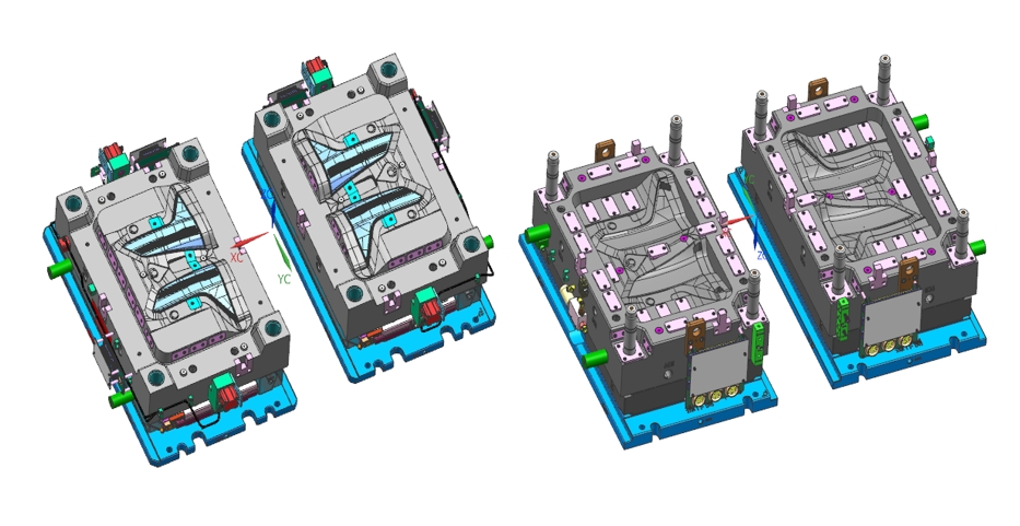
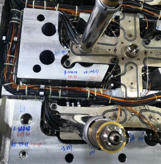
Design Considerations for Hot Runners
1. R Angle on Fixing Plate: R angles are needed to avoid cord damage and facilitate CNC machining.
2. Hot Runner Socket Positions: Ensure hot runner socket positions meet customer needs.
3. Main Nozzles Position: Main nozzles should be positioned below the panel by at least 2mm.
4. Hydraulic and Electrical Systems: These should connect at the non-operation side and not exceed clamping templates.
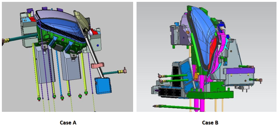
Design of Side Pulling Core Structure
Each plastic part has six undercuts with a side-core pulling structure composed of various components for stable and reliable operation.
Design Principles for Slides
1. Priority of Mechanical-Driven Structure: Mechanical-driven structures are prioritized for reliability and cost-effectiveness.
2. Conventional Slider Preference: Conventional sliders are preferred to minimize processing difficulty.
3. Moving Mold Priority: The design should follow the moving mold priority principle to minimize risks.
Temperature Control System Design
The mold temperature control system ensures uniform and rapid cooling to maintain size accuracy. The design incorporates vertical water pipes and spacer wells to enhance cooling efficiency.
Design Considerations
1. Cooling Water Direction: Consistent with material flow.
2. Cross Grid Cooling Circuits: To ensure uniform cooling.
3. Distance Between Water Circuits: Should be 3.5-5 times the diameter of the water pipes.
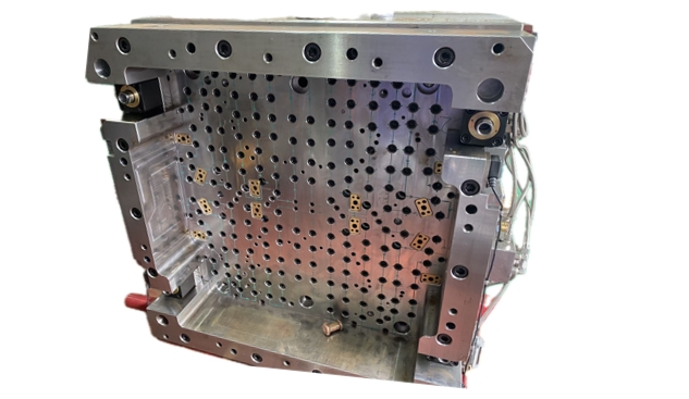
Design of Guide Positioning System
A circular guide pin is installed at the corners of the mold to ensure accurate positioning and support mold weight.
Guide Pin Functions
1. Accurate Guidance: To movable parts.
2. Support Mold Weight: To prevent deformation.
3. Protect Mold Parts: From damage.
Design of Mold Release System
The mold release system uses a push rod mechanism to eject plastic parts after mold opening.
Design Points
1. Stop-Rotation Settings: For special-shaped surface push rods.
2. Clearance on Retropinhole: To facilitate processing.
Design of Mold Base Structure
The mold base structure incorporates guide pins and auxiliary structural parts to enhance mold strength and service life.
Design Considerations
1. Process Screws: For easy operation and fitting.
2. Pressure Bearing Block: Should be designed to prevent deformation.
Design of Venting System
An appropriate venting system is crucial for ensuring quality in large-scale automotive molds.
Venting System Design Points
1. Priority Locations: At the end of material flow and corners.
2. Close to Inserts: To prevent welding marks.
Conclusion
The design of injection molds for automotive headlights involves careful consideration of various factors, including parting surfaces, pouring systems, core structures, temperature control, guide systems, mold release mechanisms, and venting systems. Each element plays a critical role in ensuring efficient production, high-quality parts, and extended mold life.
